RFQ · Engineering quote

RF & microwave terminals

RF and microwave terminals carry high-frequency signals through a hermetic wall without destroying return loss. Geometry and dielectric influence the transition from internal MMIC to external connector.

Pair with die-level thermal — laser submount catalog, datacom submounts, or order SiC/ALN samples.

Package quote

Request a hermetic package quote

Outline, volume, and application — we respond within one business day. Attach a drawing if you have one.

Context

RF & microwave terminals

Response within 1 business day · Need a full RFQ? Open detailed package RFQ →

How to choose

Share your target frequency band and connector type. Terminal pitch and glass-seal construction set the parasitics — we align the drawing to your EM model or measured coupon data.

9 outlines in catalog

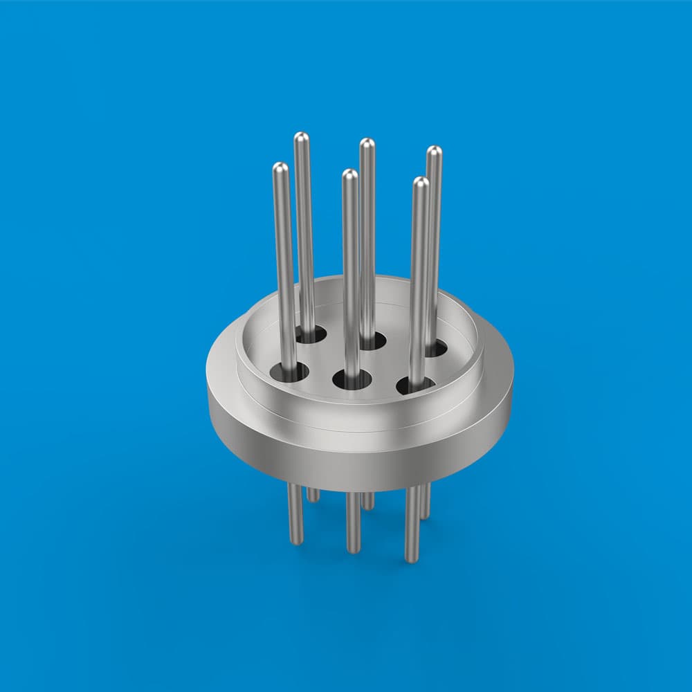
Flow Terminal Type 1

Flow Terminal Type 1

RF or microwave feedthrough terminal — Flow Terminal Type 1.

Typical use & selection notes

Typical use: High-frequency modules needing controlled-impedance pins through a hermetic wall.

Why this line: Terminal geometry sets the transition from internal MMIC to external coax or waveguide — match your stack-up model.
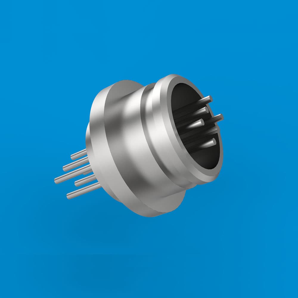
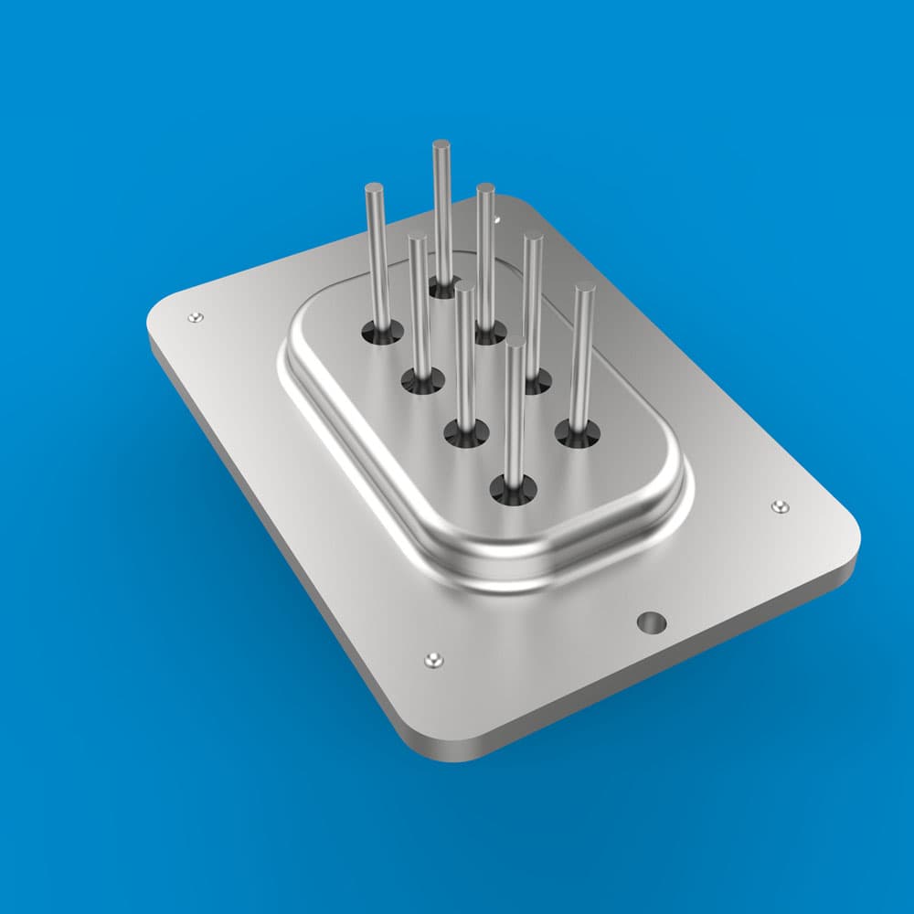
Flow Terminal Type 2

Flow Terminal Type 2

RF or microwave feedthrough terminal — Flow Terminal Type 2.

Typical use & selection notes

Typical use: High-frequency modules needing controlled-impedance pins through a hermetic wall.

Why this line: Terminal geometry sets the transition from internal MMIC to external coax or waveguide — match your stack-up model.
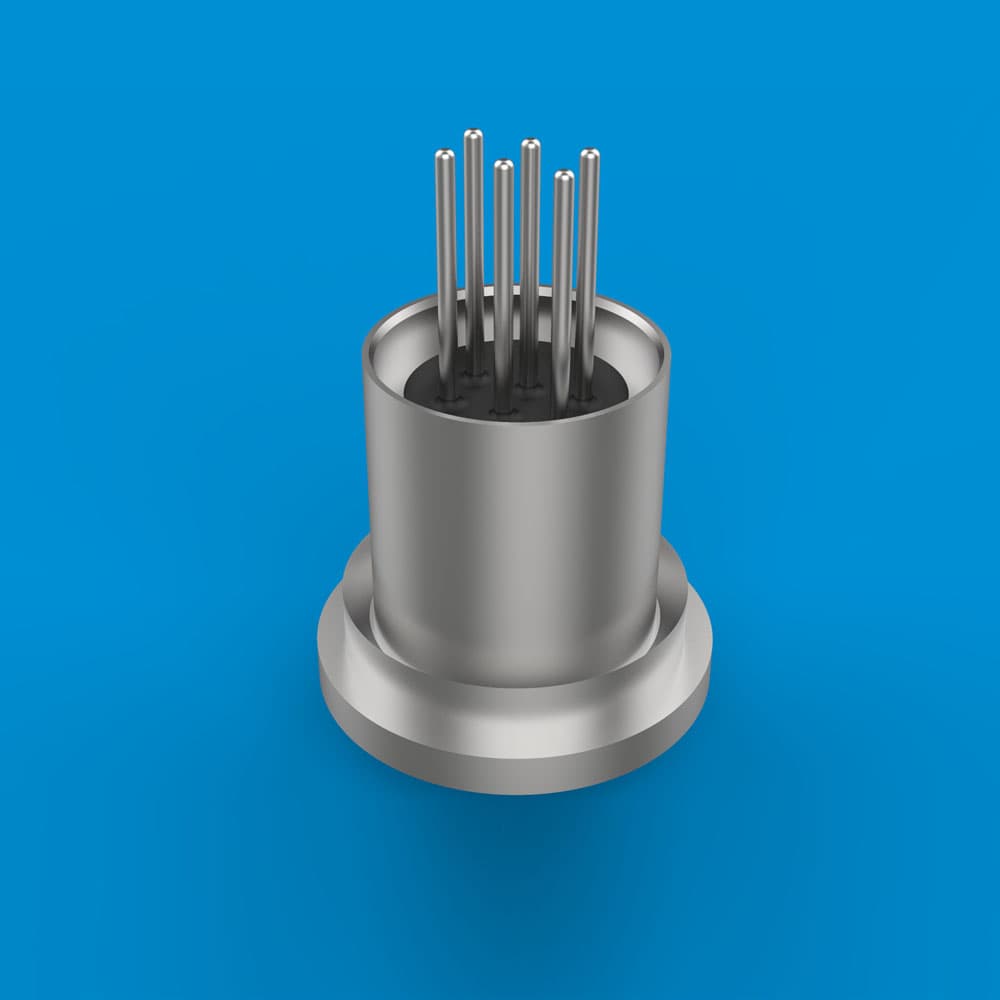
Flow Terminal Type 3

Flow Terminal Type 3

RF or microwave feedthrough terminal — Flow Terminal Type 3.

Typical use & selection notes

Typical use: High-frequency modules needing controlled-impedance pins through a hermetic wall.

Why this line: Terminal geometry sets the transition from internal MMIC to external coax or waveguide — match your stack-up model.
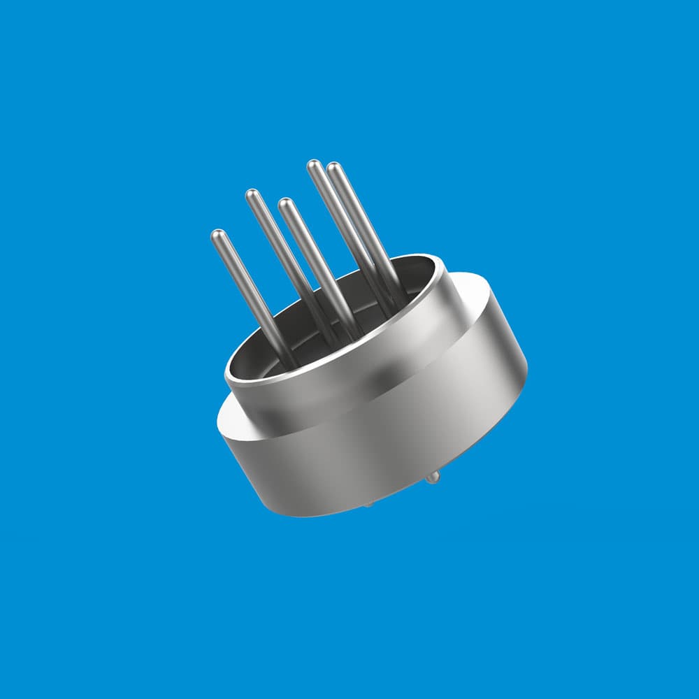
Flow Terminal Type 4

Flow Terminal Type 4

RF or microwave feedthrough terminal — Flow Terminal Type 4.

Typical use & selection notes

Typical use: High-frequency modules needing controlled-impedance pins through a hermetic wall.

Why this line: Terminal geometry sets the transition from internal MMIC to external coax or waveguide — match your stack-up model.
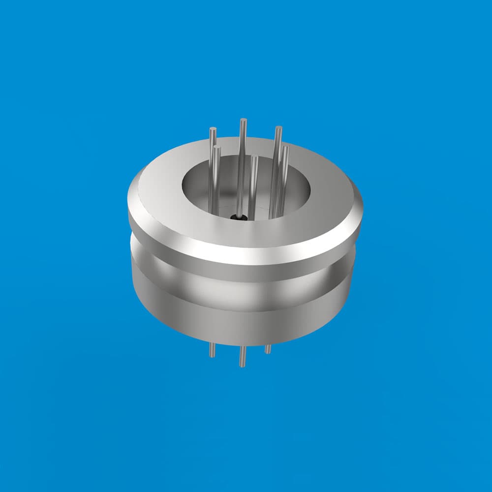
Flow Terminal Type 5

Flow Terminal Type 5

RF or microwave feedthrough terminal — Flow Terminal Type 5.

Typical use & selection notes

Typical use: High-frequency modules needing controlled-impedance pins through a hermetic wall.

Why this line: Terminal geometry sets the transition from internal MMIC to external coax or waveguide — match your stack-up model.
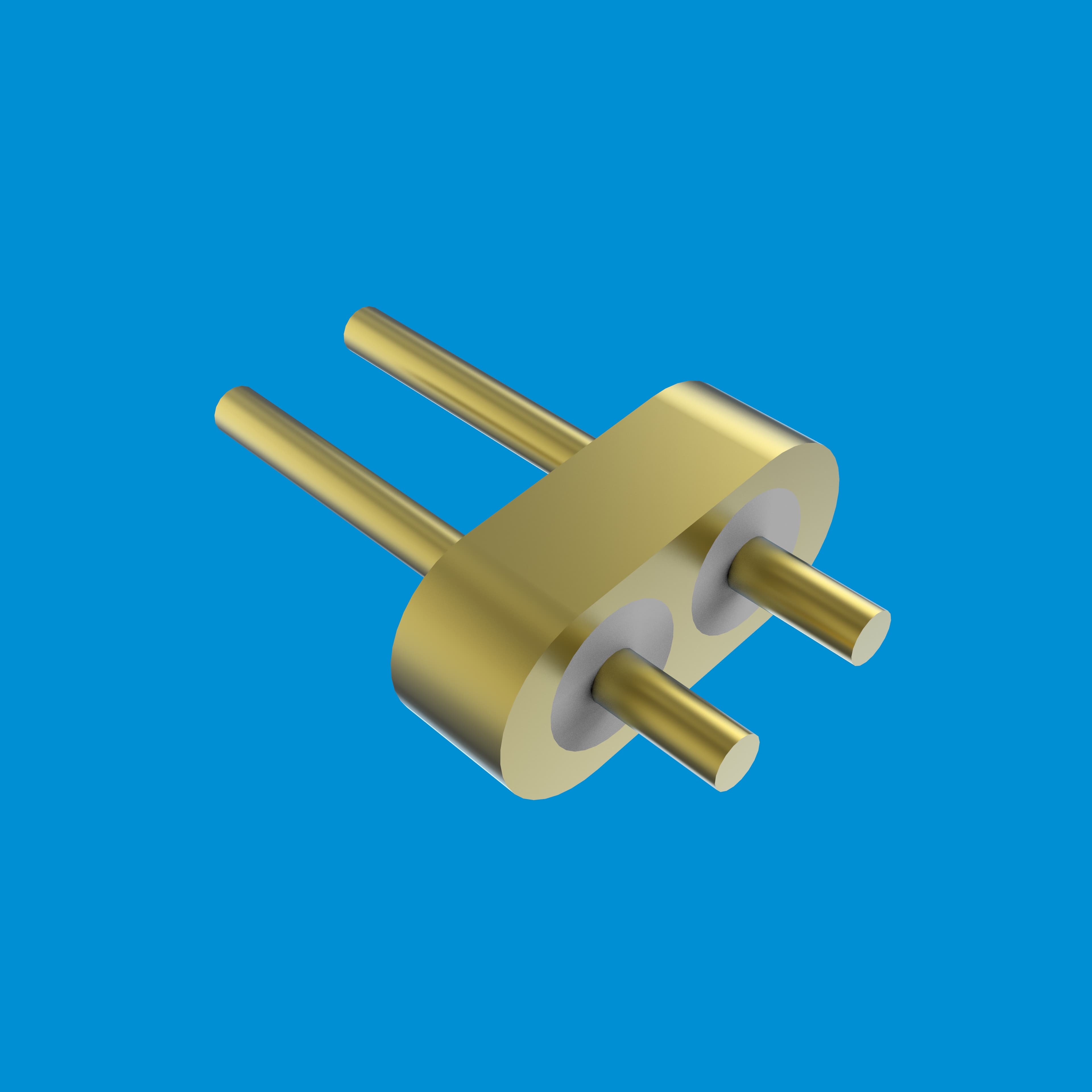
Flow Terminal Type 6

Flow Terminal Type 6

RF or microwave feedthrough terminal — Flow Terminal Type 6.

Typical use & selection notes

Typical use: High-frequency modules needing controlled-impedance pins through a hermetic wall.

Why this line: Terminal geometry sets the transition from internal MMIC to external coax or waveguide — match your stack-up model.
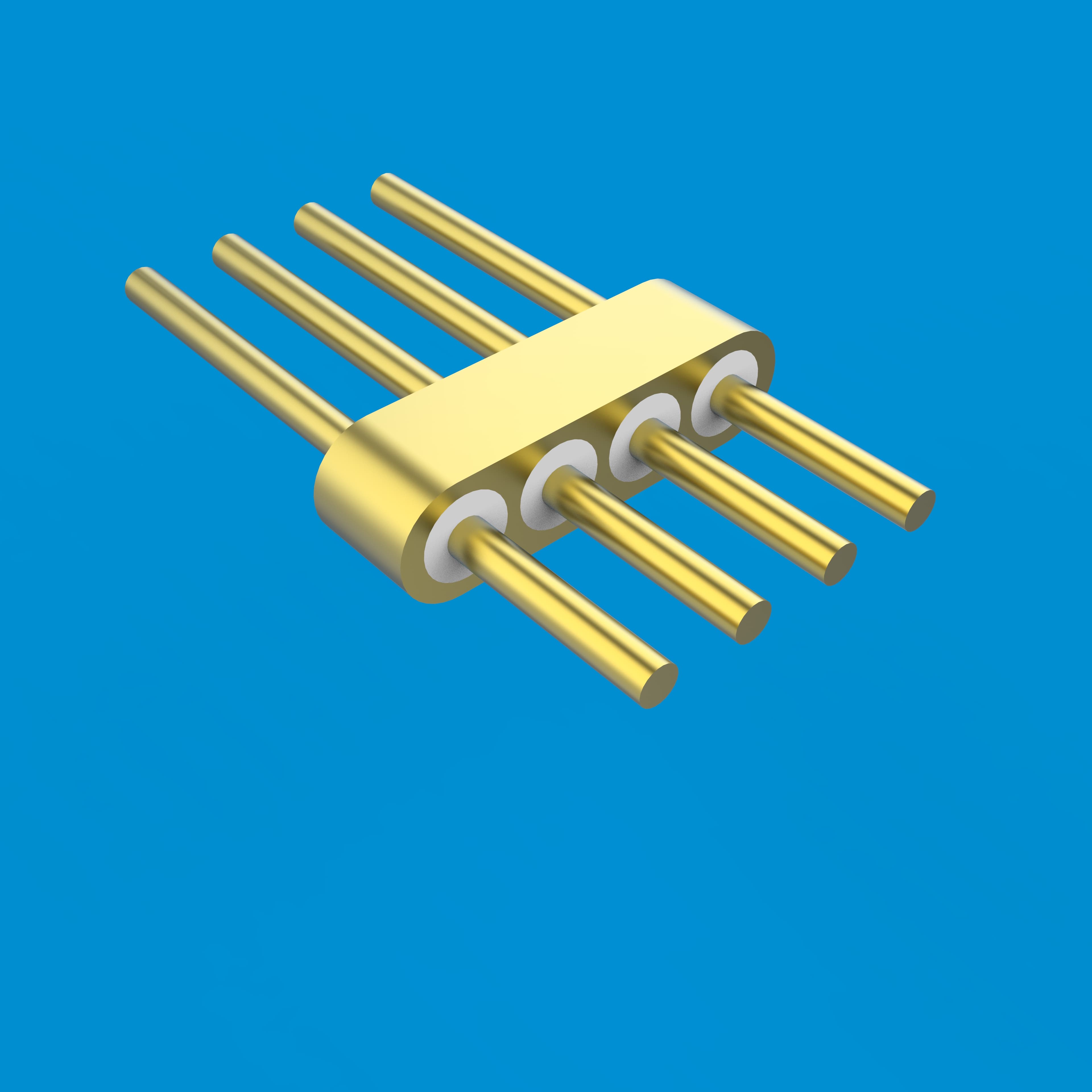
3.2×1.5-2-Pin

3.2×1.5-2-Pin

RF or microwave feedthrough terminal — 3.2×1.5-2-Pin.

Typical use & selection notes

Typical use: High-frequency modules needing controlled-impedance pins through a hermetic wall.

Why this line: Terminal geometry sets the transition from internal MMIC to external coax or waveguide — match your stack-up model.
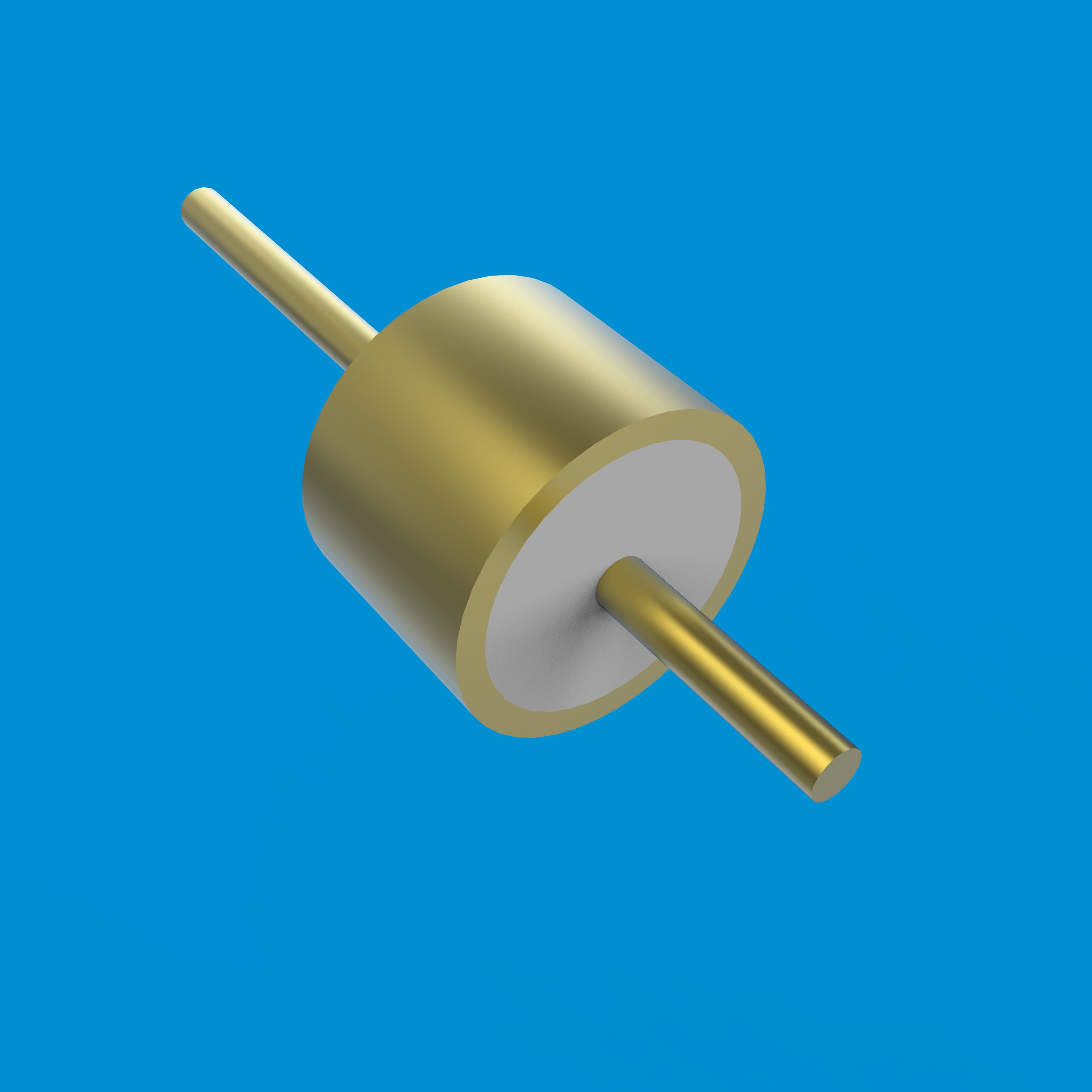
5.5×1.5-4-Pin

5.5×1.5-4-Pin

RF or microwave feedthrough terminal — 5.5×1.5-4-Pin.

Typical use & selection notes

Typical use: High-frequency modules needing controlled-impedance pins through a hermetic wall.

Why this line: Terminal geometry sets the transition from internal MMIC to external coax or waveguide — match your stack-up model.

φ1.93-1-Pin

φ1.93-1-Pin

RF or microwave feedthrough terminal — φ1.93-1-Pin.

Typical use & selection notes

Typical use: High-frequency modules needing controlled-impedance pins through a hermetic wall.

Why this line: Terminal geometry sets the transition from internal MMIC to external coax or waveguide — match your stack-up model.

RF & microwave terminals

Get quote